
Field notes / US
Grab Bar Installation Handoff Checklist for US Projects
A pre-installation handoff checklist for specifiers and installers: substrate, backing, layout, and manufacturer instructions under the 2010 ADA Standards.
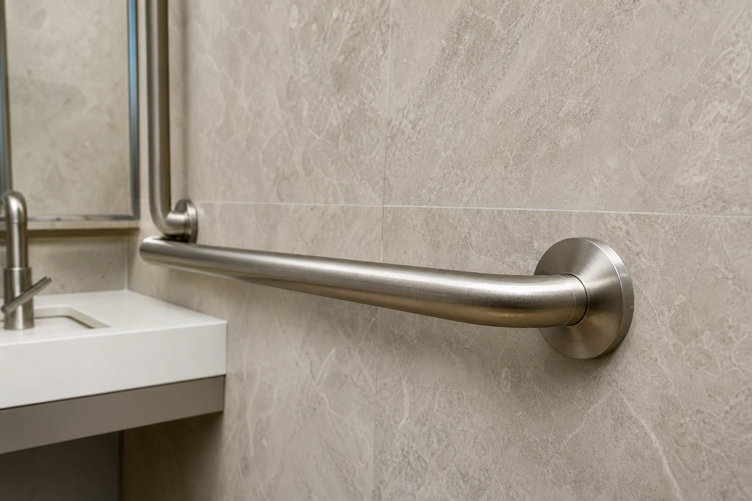
A successful grab bar installation starts long before anyone drills a hole. On US projects subject to the Americans with Disabilities Act, the specifier and the qualified installer need a clear handoff: confirmed substrate, verified backing, coordinated layout, and the manufacturer's model-specific instructions on site. This checklist helps both parties close those gaps before installation day.
Know the Standard That Applies
The US Department of Justice issued its ADA Standards for Accessible Design in 2010, and the US Access Board publishes the official combined text at https://www.access-board.gov/ada/. Section 609 addresses grab bars. Note that section 610 covers seats, not grab-bar requirements, so it should not be cited when specifying rails.
Key provisions a specifier should confirm in the drawings and specifications include:
- Grip size: Section 609.2.1 sets the outside diameter of a circular grab bar between 1.25 and 2 inches, with 32 and 51 mm given in the standard.
- Height: Section 609.4 generally measures horizontal grab bar height to the top of the gripping surface, between 33 and 36 inches (840 and 915 mm) above the finish floor.
- Structural strength: Section 609.8 assesses the grab bar, fasteners, mounting, and supporting structure under a 250 pound (1112 N) force.
Separate provisions apply to children's water closets and the lower bathtub back-wall rail, so the 33 to 36 inch height range should not be applied to those exceptions. The requirements describe what the installed assembly must achieve; they are not, by themselves, evidence that a particular product or installation is compliant.
Confirm the Substrate Before Order
The substrate determines what backing, fastening approach, and structural verification the assembly will need. Before the order is placed, the specifier and installer should confirm:
- The wall construction type at each grab bar location, such as stud framing, masonry, tile over a substrate, or another build-up defined by the project designer.
- The finished floor level at each location, since grab bar height is measured to the top of the gripping surface above the finish floor.
- Any wet-area conditions, waterproofing layers, or lining systems that affect how backing and mounting are coordinated.
- Who is responsible for verifying that the wall, fasteners, and mounting can meet the structural requirement in section 609.8. This is a decision for the project designer and a qualified installer, not a matter the product sheet alone can settle.
If substrate conditions vary between rooms or floors, record them per location rather than assuming one detail covers the whole project.
Plan Backing and Blocking Early
Backing is the part of the handoff most often missed. Reinforcement must be in the wall before finishes close in, so the layout has to be fixed early enough for the framing or wall contractor to act on it.
The handoff should confirm:
- Exact rail positions and lengths for each location, shown relative to fixtures and the finish floor, consistent with the applicable scoping documents and the 2010 ADA Standards.
- The orientation of each bar, since wall and bathtub provisions differ and the lower bathtub back-wall rail is treated separately.
- How the backing aligns with the intended mounting points of the selected rail, so fasteners land on structure rather than on unsupported finish.
- Whether the blocking layout accommodates the manufacturer's required mounting configuration for the chosen model.
Because section 609.8 assesses the bar, fasteners, mounting, and supporting structure as an assembly, backing that is roughly placed but not coordinated with the rail's fixing points can undermine the whole installation.
Put Manufacturer Instructions in the Handoff
Dimensions in a specification describe the product category; they do not describe a specific model. Before installation, request model-specific information from the manufacturer, including installation instructions, fixing configurations, and any guidance the manufacturer provides for the chosen rail. Flanso does not publish a general dimension sheet that substitutes for this step: ask for the documentation specific to each model through https://flanso.com/#anchoring.
The handoff package should include:
- The selected model references and the manufacturer's instructions for each.
- The relevant sections of the 2010 ADA Standards, available at https://www.access-board.gov/ada/.
- The project designer's details for backing, finishes, and floor levels.
- Confirmation of who will verify the completed assembly against the structural requirement in section 609.8.
Keep Layout Verification on Site
On installation day, the qualified installer should verify the layout against actual site conditions before fixing begins. Finished floor levels, tile build-ups, and fixture positions can differ from the drawings. Confirming heights to the top of the gripping surface, positions relative to fixtures, and alignment with backing at each location protects the project from rework and from assemblies that look right but measure wrong.
Any deviation found on site, such as a floor level change or misplaced blocking, should go back to the project designer for a decision rather than being adjusted informally.
Pre-Installation Handoff Checklist
- Confirm the project's accessibility requirements and cite the 2010 ADA Standards, section 609, as published at https://www.access-board.gov/ada/.
- Confirm grip diameter selection within the 1.25 to 2 inch range in section 609.2.1, or the equivalent given in mm.
- Set horizontal rail heights within the 33 to 36 inch (840 to 915 mm) range in section 609.4 where it applies, and check the separate provisions for children's water closets and the lower bathtub back-wall rail.
- Record substrate and wall build-up for each grab bar location.
- Coordinate backing and blocking with the selected model's mounting points before finishes close in.
- Request model-specific installation information from the manufacturer; do not rely on category descriptions. Contact Flanso via https://flanso.com/#contact.
- Assign responsibility for verifying the bar, fasteners, mounting, and supporting structure against section 609.8 to the project designer and qualified installer.
- Verify final positions on site against finish floor levels and fixture locations before fixing.
For questions about specific Flanso models or to request model-specific documentation for your project, get in touch at https://flanso.com/#contact. Illustrative photos in catalogues and on site do not by themselves demonstrate that an installation complies; measured verification against the standards does.