
Field notes / US
Grab Bar 36 Inch: Matching Rail Lengths to US Commercial Washroom Layouts
How to choose grab bar lengths for a US commercial washroom project: layout fit, the official ADA sections that apply, and what to confirm in submittals before ordering.
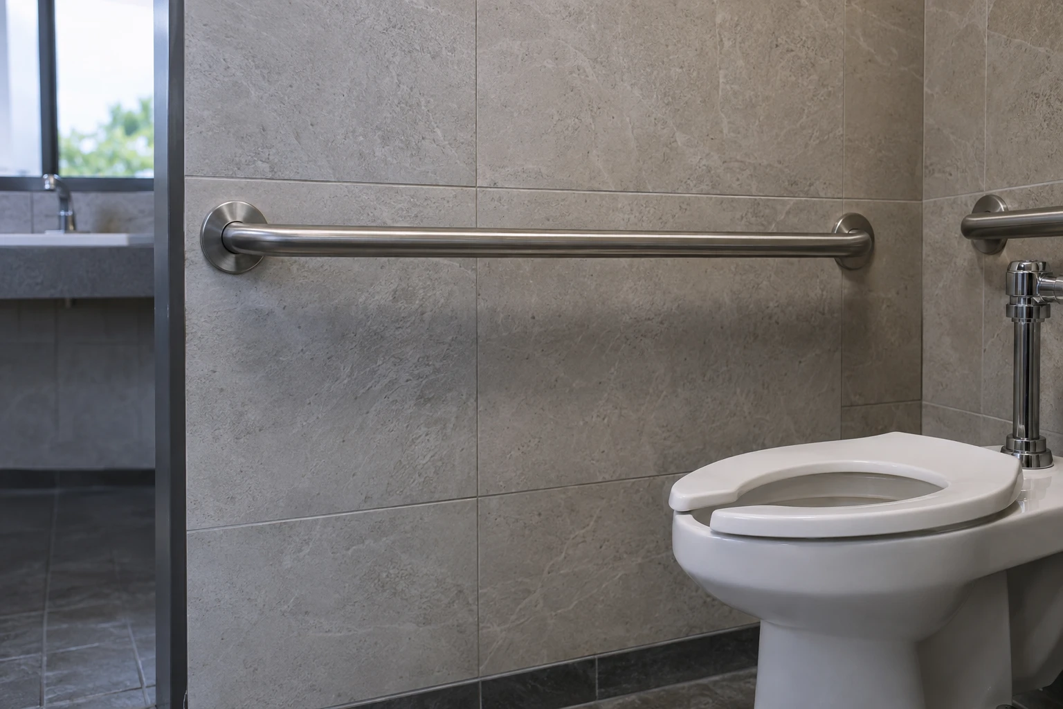
A 36 inch grab bar is a common length on commercial schedules, but the right length for any position depends on the fixture, the transfer direction and the clearances in your layout. In the United States, the requirements that govern placement and length are the 2010 ADA Standards issued by the US Department of Justice, published by the US Access Board at https://www.access-board.gov/ada/. This article covers how to match rail lengths to a commercial washroom layout and what to confirm in submittals before you order. Structural and installation decisions belong with your project designer and qualified installer.
Start with the layout, not the catalogue
Rail length is an output of the plan, not an input. Before looking at product pages, mark on your drawings:
- Which fixture each rail serves: water closet, shower, bathtub or transfer point
- The direction of the expected transfer and the wall available beside and behind the fixture
- Door swings, partitions, ducts and other obstructions that could shorten a usable wall run
- Finished wall build-ups, since finished floor level and surface depth affect every measured dimension
A 36 inch rail may suit one water closet position and be wrong for the next, even in the same building. Confirm positions against the applicable sections of the ADA Standards rather than copying a previous schedule.
What the ADA Standards actually cover
The official combined ADA Standards text is maintained by the US Access Board at https://www.access-board.gov/ada/. For grab bars, the relevant provisions sit in section 609. Note that section 610 addresses seats, not grab-bar requirements, so do not cite it for rail placement or length.
Key points specifiers should read directly from the standard:
- Section 609.2.1 sets the circular outside diameter of the gripping surface between 1.25 and 2 inches, with 32 and 51 mm given in the standard.
- Section 609.4 generally measures horizontal grab bar height to the top of the gripping surface, between 33 and 36 inches (840 and 915 mm) above the finish floor. Separate provisions apply to children's water closets and the lower bathtub back-wall rail, so this range does not apply to those exceptions.
- Section 609.8 assesses the grab bar, fasteners, mounting and supporting structure under a 250 pound (1112 N) force. This is a requirement of the standard, not a product test result.
Where a rail starts and stops relative to the fixture, and which lengths satisfy each configuration, is set out in the standard's provisions for each fixture type. Your project designer should confirm the exact configuration against the current official text.
Why a 36 inch rail may or may not be the answer
Length choices fail in two directions. A rail that is too short can leave the gripping surface ending before the user needs support. A rail that is too long can conflict with clearances, adjacent fixtures or a side wall, or push the mounting into a wall cavity with no suitable backing.
For each position, verify:
- The wall run available once finished surfaces and obstructions are accounted for
- Whether the required configuration calls for a side wall rail, a rear wall rail or both
- That the rail's mounting brackets land where backing or structure can be provided
Also remember that section 609.4's height range interacts with length: a longer horizontal rail still sits with its top gripping surface within the specified height band above the finish floor.
Wall construction and the 250 pound requirement
Length and diameter mean little if the wall cannot support the rail. Section 609.8 applies its force requirement to the complete assembly: the bar, the fasteners, the mounting and the supporting structure. That means the substrate review happens in the project, not in a product datasheet.
Coordinate early between the specifier and the qualified installer:
- Identify the wall assembly at each rail position, including any concealed framing or backing
- Agree where reinforcing will be installed, and document it on the drawings
- Confirm the manufacturer's installation requirements are available for the chosen model before fixings are ordered
Flanso provides an anchoring overview at https://flanso.com/#anchoring as a starting point for these conversations, but the fixing design itself must be confirmed by the project designer and qualified installer for the actual wall construction.
What to confirm in submittals before ordering
A submittal is where length, finish and evidence come together. Before releasing an order, check that the submittal includes:
- The exact model reference and length for each rail position, matched to the drawing schedule
- Dimensioned drawings showing gripping surface diameter, which must fall within the section 609.2.1 range of 1.25 to 2 inches
- Confirmation of the wall type and fixing method intended at each position
- Any manufacturer installation instructions relevant to the model
Treat any claim that a product is "ADA compliant" as a starting point, not proof. Compliance is assessed against the standard's requirements in the context of the installed assembly, including the wall. Do not assume a catalogue drawing demonstrates that a completed installation meets section 609.8.
A project checklist for rail lengths
Before ordering rails for a US commercial washroom project:
- Confirm the governing standard and read the grab-bar provisions at the official source: https://www.access-board.gov/ada/
- Mark each rail position on the plan with fixture type and transfer direction
- Check the available wall run at each position against the proposed length
- Verify gripping surface diameter against section 609.2.1
- Confirm height set-out per section 609.4, and check whether any exception applies
- Review wall assemblies and backing with the qualified installer
- Reference the section 609.8 force requirement as a design requirement for the complete assembly
- Assemble submittals with model references, drawings and installation instructions per model
- Keep the sign-off for final positions and fixings with the project designer and installer
For model-specific information on lengths, finishes and documentation, request details from Flanso at https://flanso.com/#contact.